Untitled
Workflows, Best Practice guidance, Tips and Tricks to extract the best from Hammer Missions
Mission Planning (Roof and Facade Mapping)
In this tutorial we will walk you through the process for creating the Roof and Facade mapping flight plans that will allow you to create a high‑quality 3D model via the Hammer platform. This guide covers everything from drawing the mission boundary to setting camera and flight parameters, running a simulator check and combining roof and facade captures for seamless photogrammetry results.
If you prefer to watch a video on this topic use the link immediately below, otherwise skip over it to the Blog article
https://www.loom.com/share/6065399896ee4c5ebae86e59a5246dd1?sid=2222d0b3-2ee1-4c32-91c2-e094549ae3d9
Overview: What you'll achieve
By the end of this guide you'll be able to:
- Create a roof mapping mission that captures roof detail with the necessary side aspect for effective 3D model joining of the facades.
- Create one or more facade mapping missions to capture the building sides with the correct overlap and distances.
- Configure camera, altitude, overlaps, gimbal tilt and flight direction for reliable photogrammetry.
- Use the flight path simulator to preview the flight plan.
1. Start a new flight mission (roof)
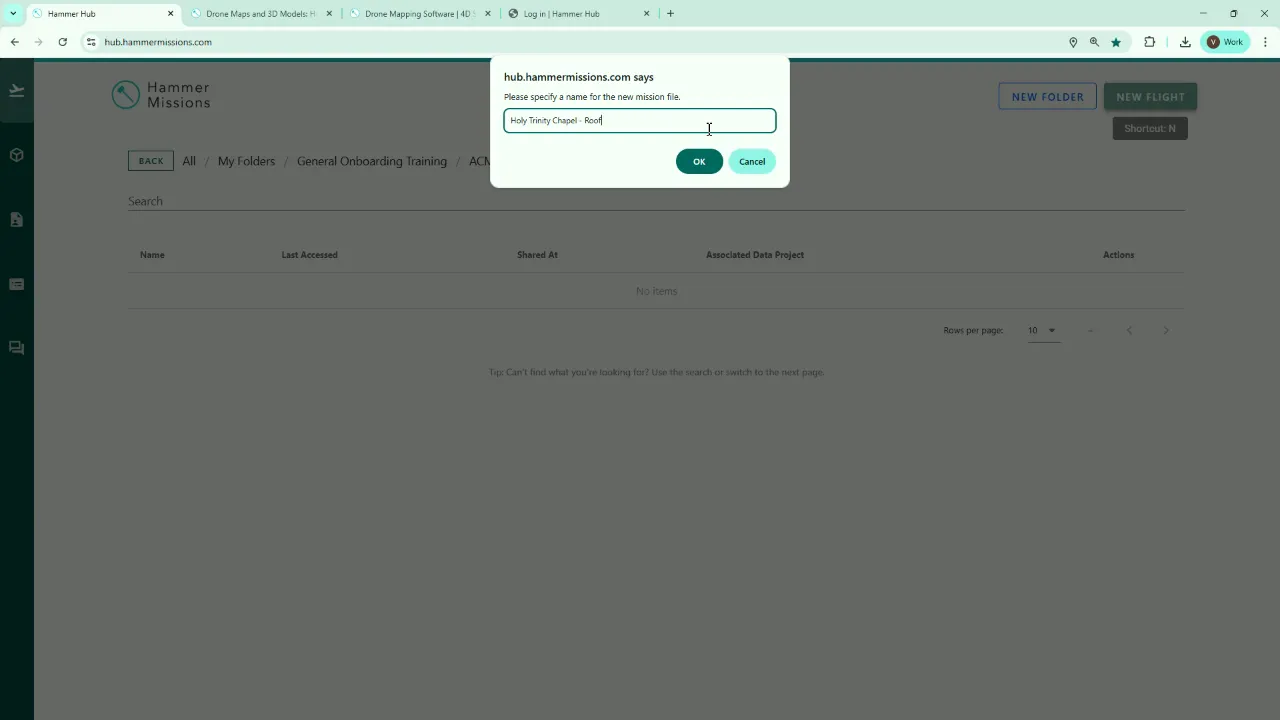
Begin by clicking New Flight and give the mission a clear name — for example, "Holy Trinity Chapel - Roof". This makes mission management easier when you have multiple flights for the same structure.
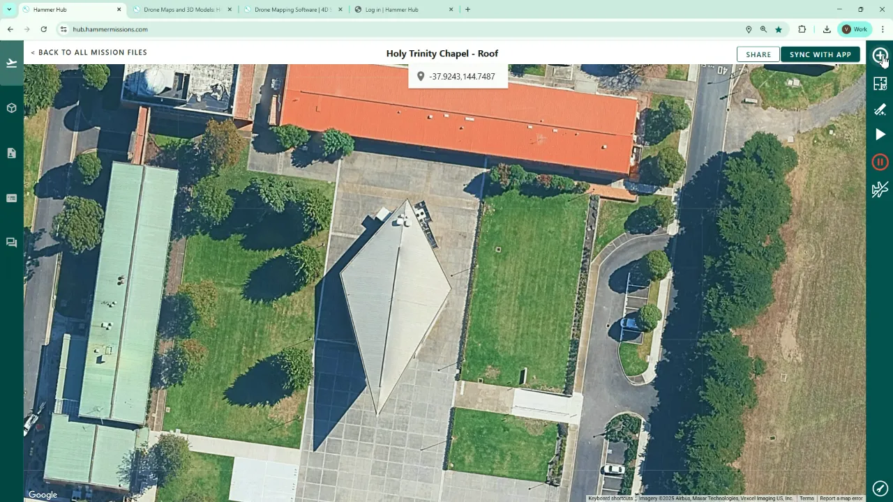
Search for the site address in the planning search box and zoom to the building. For my example the church is a diamond/elliptical shape on the map. Once you have the building in view, click the plus icon in the right hand green panel and choose Mapping.
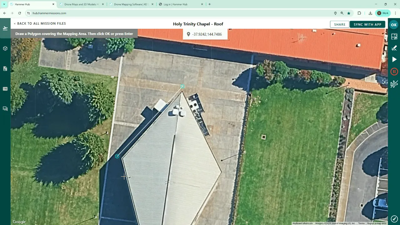
Outline the roof boundary
Click around the building to draw the boundary. We recommend drawing just a little beyond the visible boundary on the map — this helps later when joining roof and facade captures so that both datasets have overlapping areas.
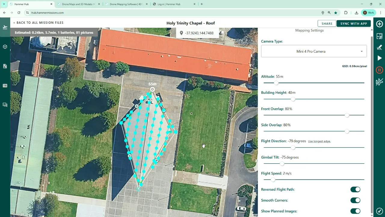
2. Configure the roof mission parameters
Click the cog icon to set mission‑specific parameters.
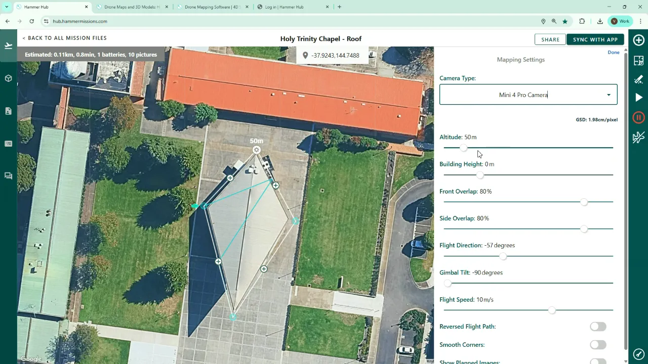
- Camera: Select the camera you’ll fly with (in our case the DJI Mini 4 Pro).
- Building height vs flight height: It helps to know the highest point of the building. If unknown, perform a quick provisional flight to measure the height and check for hazards. For this example the highest point is ~40 m, and we set the flight altitude to 55 m (≈15 m above the highest point).
- GSD: Ground Sampling Distance is auto‑calculated as you change building and flight height; keep an eye on it to ensure that image resolution meets your project needs.
- Front and side overlap: This is critical — it’s the common area between adjacent images. We recommend at least 70–80% overlap to give the photogrammetry engine a good chance of matching features and producing a clean 3D model.
- Flight direction: Choose the orientation the aircraft will fly. You can rotate the flight lines to match building geometry or wind/operational constraints.
- Gimbal tilt: For roof mapping you usually set 90° (straight down). We recommend something around 70–75° to capture some side aspect detail — this helps the process to join roof and facade datasets.
- Flight speed: The system suggests an optimal speed based on your settings, but you can reduce it if needed.
- Reverse flight path: Toggle this if you want the mission to start from the diagonally opposite side of the building.
- Smooth corners: Rounds off turns for smoother transitions and more efficient flight.
- Show planned images: Tick this to visualise exact image capture points on the map.
Once configured, save the mission. In the top right corner of the screen, you can see an estimated distance, flight time, battery count and number of photos for the mission.
3. Why extend the roof boundary a little
Going slightly beyond the apparent building footprint is intentional. If you plan to generate a full 3D model, then both the roof and facade captures must share overlapping image areas so the photogrammetry software can stitch them together smoothly.
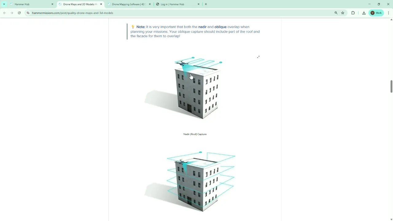
By tilting the gimbal slightly (~75°) on the roof mission and extending the boundary, roof passes capture some of the vertical surface near the top of the facade. Likewise, facade passes capture a little of the roof at their uppermost lines — that overlap is essential for a clean join.
4. Preview the mission with the simulator
Before leaving the planning environment, click the Simulator. This gives:
- A 2D map route and flight lines
- A 3D preview of the mission geometry
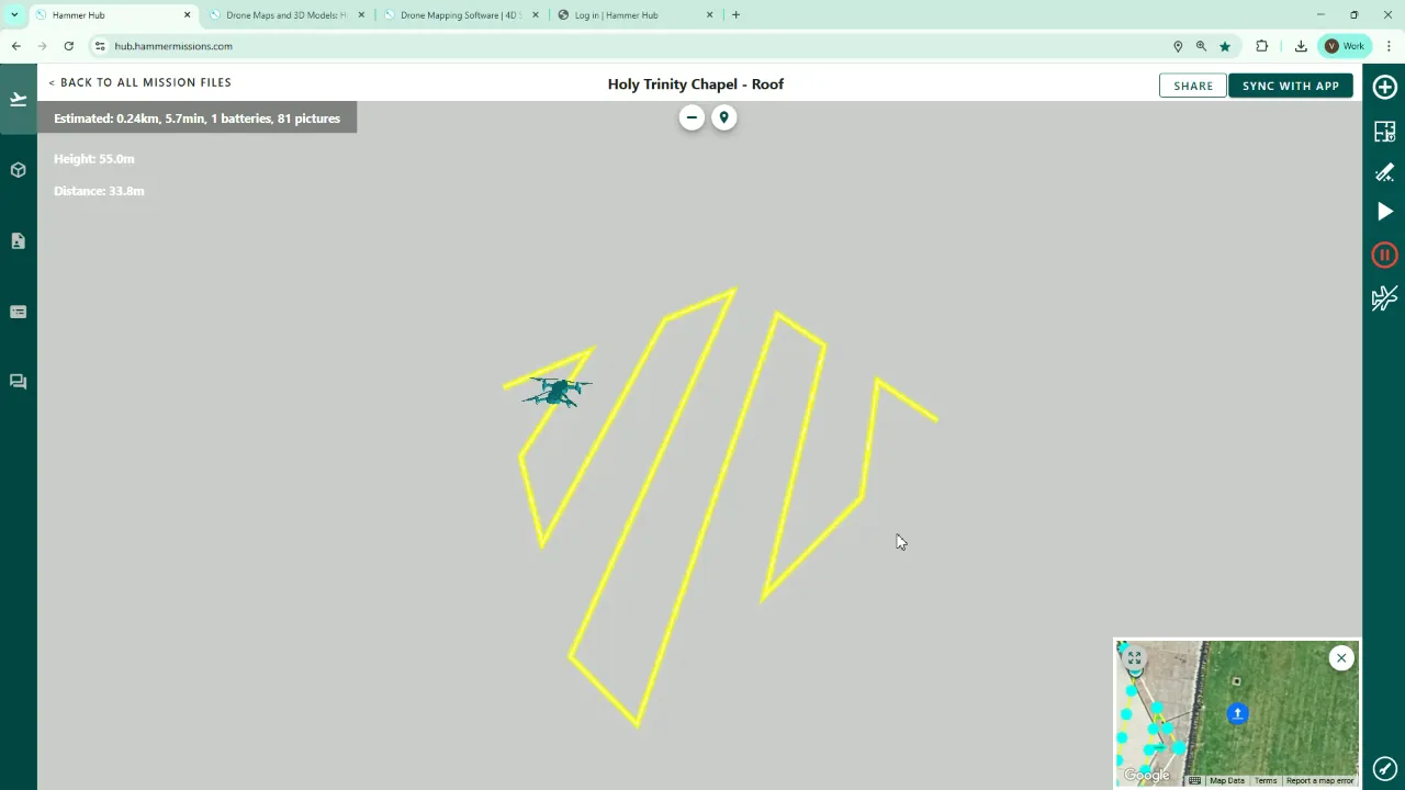
The simulator is excellent for pilot briefings so everyone understands how the drone will execute the mission and where images will be captured.
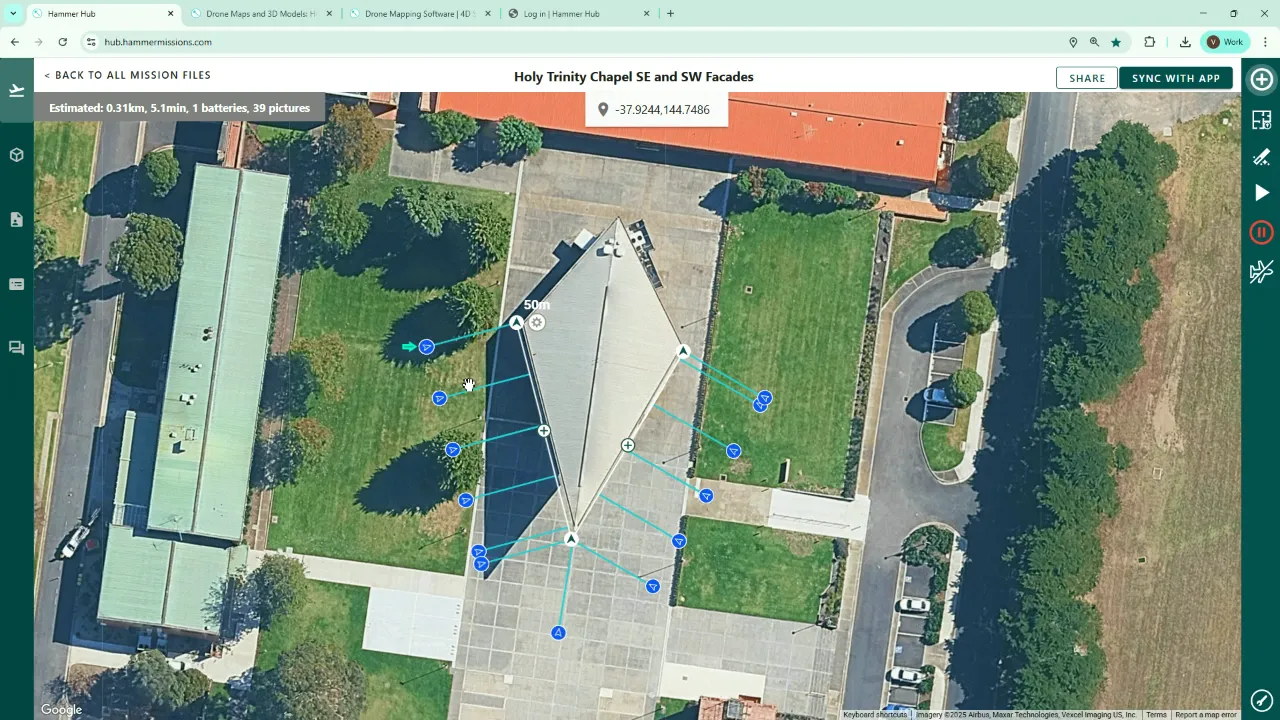
5. Create facade missions
Next, create one or more facade missions. In our example we created a combined "Southeast and Southwest facades" mission because a pilot standing at the southern edge can often cover both facades while remaining within Visual Line Of Sight (VLOS).
You can also create single facades (e.g., southeast, southwest, northeast, northwest) if operational or regulatory constraints require it.
Drawing facade flight paths
Click the plus icon (top right corner) and choose Facade Mapping, then click points around the facade sections that you want to capture. When you accept, the system displays lines extending from the facade — these represent drone positions when images are captured.
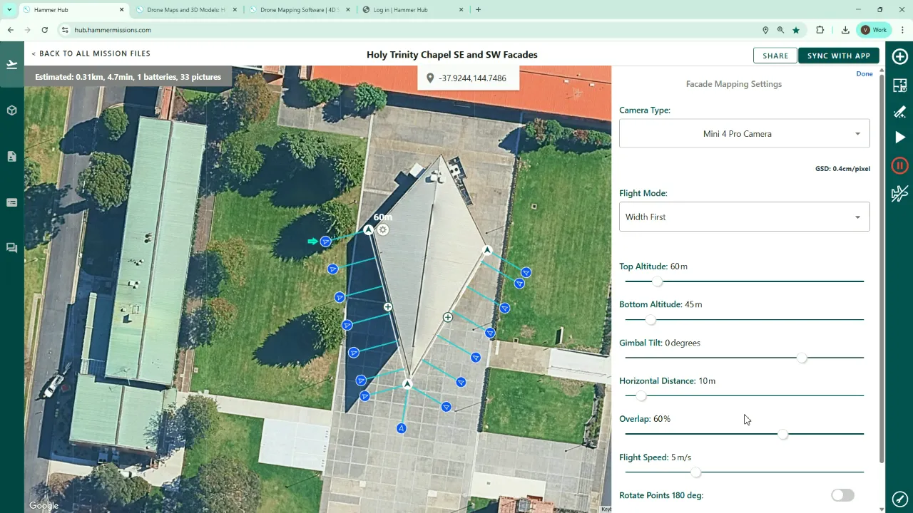
6. Configure facade mission parameters
Open the cog and configure these key settings:
- Camera: Select your drone camera (Mini 4 Pro in my example).
- Width first vs Height first: Choose the traversal pattern:
- Width first: Fly along the facade horizontally, then move down/up to the next strip. Efficient for short‑long walls.
- Height first: Fly top‑to‑bottom then shift horizontally. Efficient for tall, narrow facades.
- Top and bottom altitudes: Set the highest and lowest altitudes of the facade passes. We increased the top altitude slightly (to capture some roof detail) and set the bottom altitude based on site obstacles — (e.g. trees or street furniture may force adjustments).
- Gimbal tilt: Typically 0° for facades (camera pointing directly at the wall).
- Horizontal distance: How far from the facade the drone will fly. This affects GSD — reducing distance improves detail but may require more passes and takes longer.
- Overlap: Again aim for ≥70–75% overlap between adjacent images for robust photogrammetry.
- Flight speed: Reduce if needed; the platform will suggest an optimal speed based on your settings.
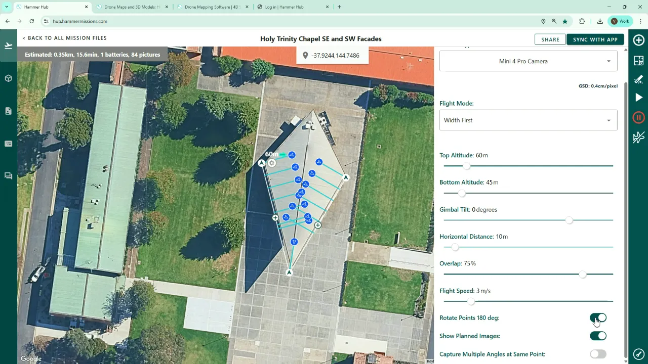
When you reduce horizontal distance (e.g., to 10 m), GSD improves (smaller metres/pixel value) and the tool updates that value live so you can balance resolution against flight time and number of photos.
Rotate capture points if needed
If the capture points are facing the wrong way — i.e., pointing from inside to outside — use the rotate option to flip them. This corrects any orientation errors the tool created automatically.
7. Best practices and tips
- Always do a quick site reconnaissance flight (or visually inspect from the ground) to confirm building height and spot obstacles before committing to the mission heights and altitudes.
- Use at least 70–75% overlap (front and side) for reliable photogrammetry stitching.
- Capture a little extra area at boundaries to ensure roof and facade datasets overlap — small extensions save on additional image re-capture effort later.
- Consider gimbal tilt strategy: slightly off‑nadir on roof missions (~70–75°) helps capture facade junctions; 0° is typical for facades.
- Use the simulator for flight crew briefings and to confirm start/finish locations, turns and capture points.
- Keep flight speeds conservative when you need high‑detail GSD; the planner will usually suggest a suitable speed.
Conclusion
Combining a carefully planned roof mission with one or more facade missions is the most reliable way to build an accurate 3D model of a building in Hammer. Name your missions clearly, verify building heights on site, aim for strong image overlap, and use the simulator to validate your plan. By following these steps you’ll give the photogrammetry process the best possible data to produce clean, joined roof and facade models.
"Front and side overlap... you want to have a good overlap, typically at least seventy five percent to ensure that the photogrammetry process... has got a good chance of joining together all those images into the model."
➡️Next Topic
Mission Planning (Additional Tools)
⬅️Previous Topic
Creating Mission Folders