Workflows, Best Practice guidance, Tips and Tricks to extract the best from Hammer Missions
In this guide we walk you through some of the essential tools and workflows you can use within Hammer Missions, for working with a 3D model and its 2D map. Whether you’re inspecting façades for defects, annotating issues or taking measurements, these practical tips will help you move faster and produce cleaner results.
If you prefer to watch a video on this topic use the link immediately below, otherwise skip over it to the Blog article
https://www.loom.com/share/cd7558319b98447e8950bef3f2659902?sid=c0af1876-92ed-42ef-84db-c43a52bc2893
The platform offers two primary views:
Throughout this article, we will cover navigation around your model, façade workflows, tagging and annotation tools, plus the measurement utilities you have at your disposal.
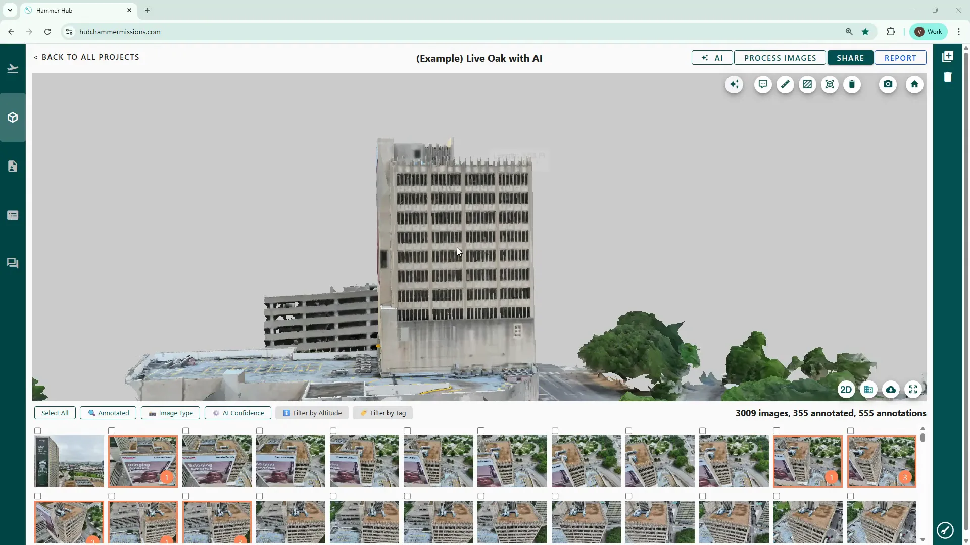
Start by opening your project in the Data Analysis section. Position your mouse cursor near the centre of the model before trying to move it — this keeps rotations smooth and avoids the “oval” rotation effect that happens when the cursor is off-centre.
Mouse controls:
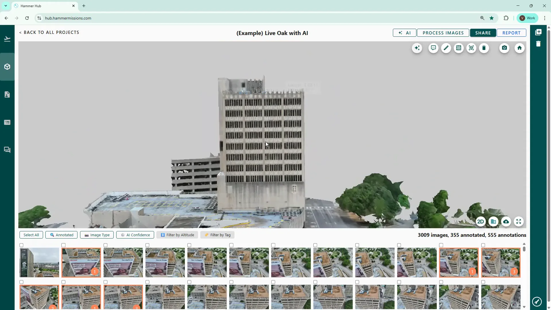
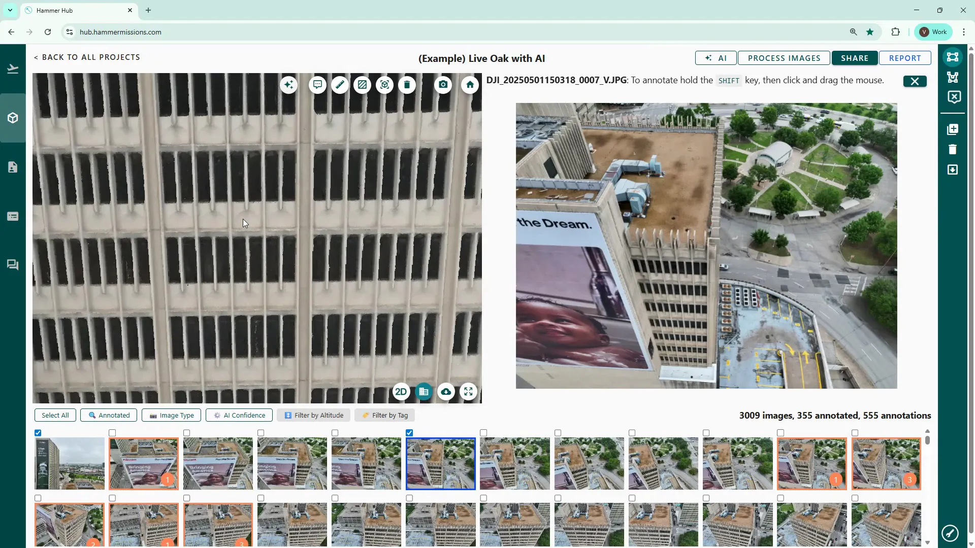
Click the 2D icon to change to a plan or orthographic view of the model area. The 2D map is useful when you want a bird’s-eye context or need to quickly reference raw drone imagery.
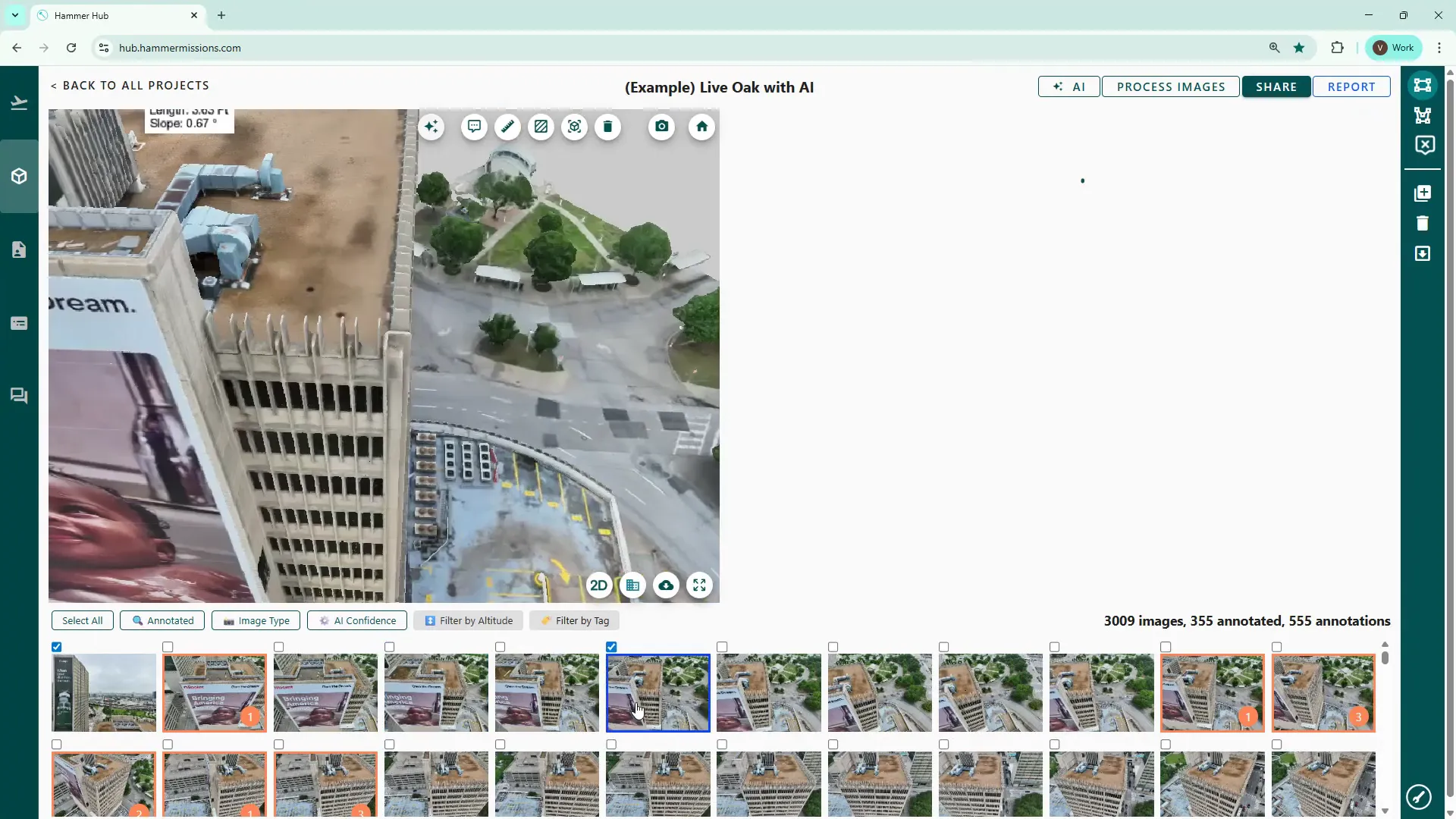
Click any thumbnail below the model to switch to a split-screen view: the 3D model on the left and the selected thumbnail image on the right. This is the normal inspection view we use when marking up deficiencies.
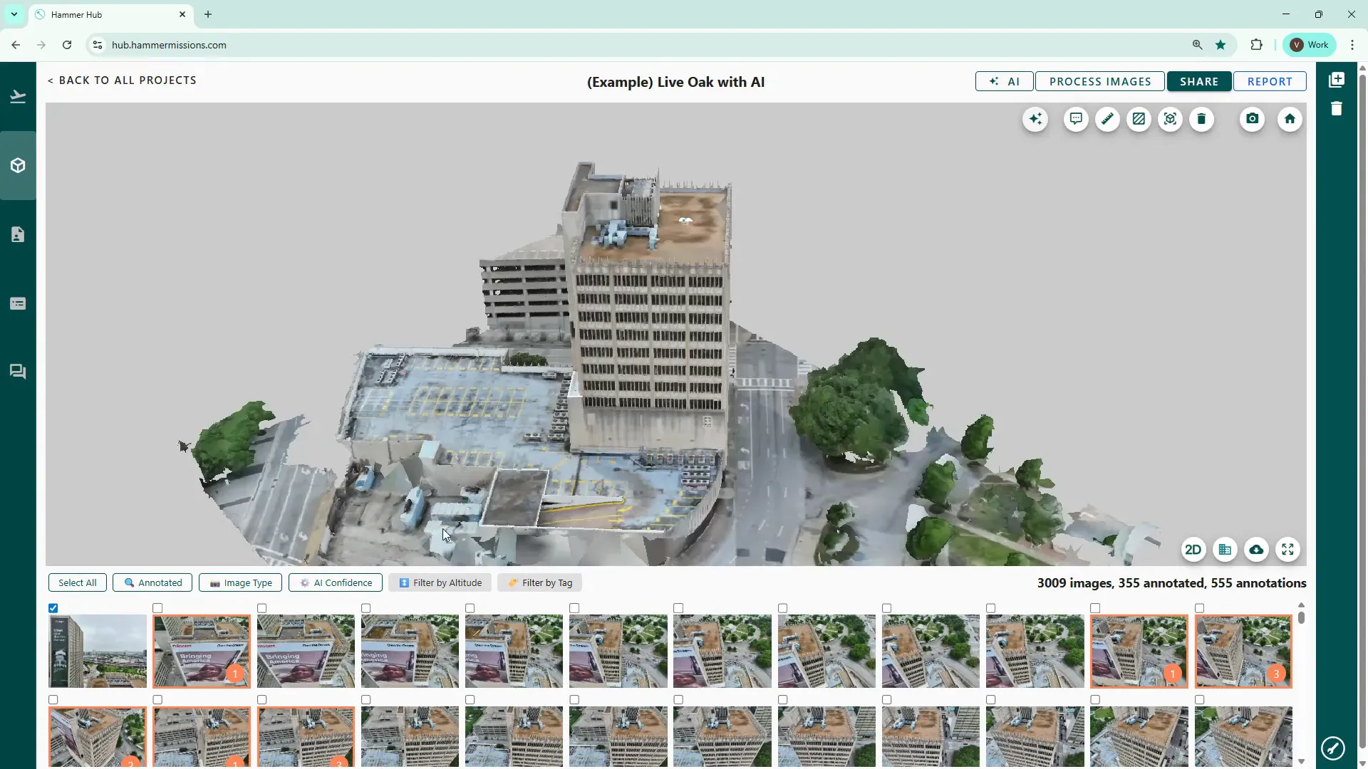
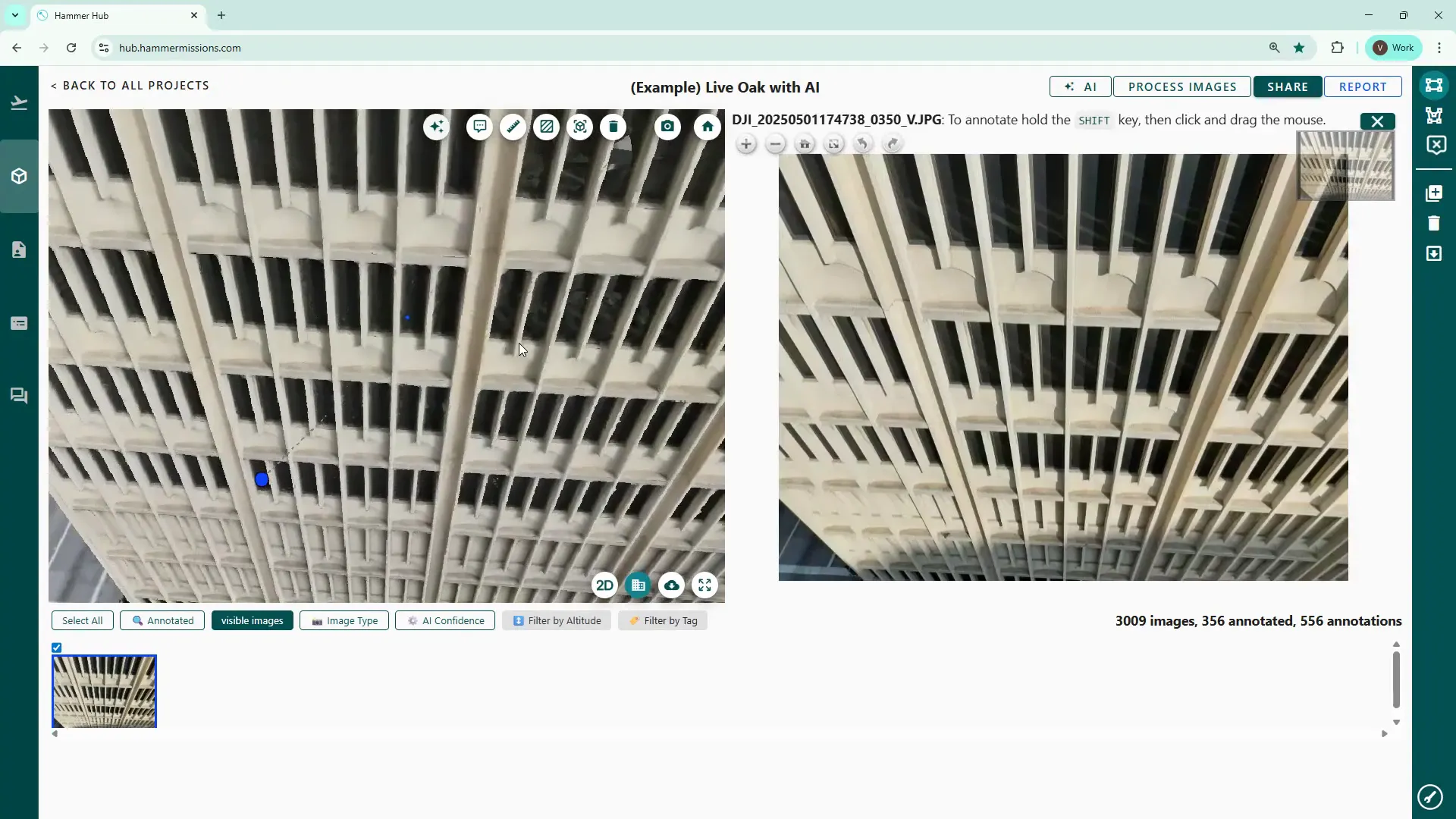
When inspecting and identifying deficiencies within your model, work through each façade and the roof area, one at a time:
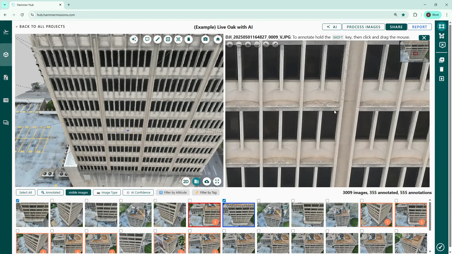
In 3D model view, the platform shows a small blue indicator at the point where you clicked the 3D model, whilst simultaneously loading the corresponding drone image in the right hand pane. The right hand pane is where you would normally zoom in and inspect, then annotate any deficiencies or other potential issue.
Tagging is straightforward and essential for later reporting:
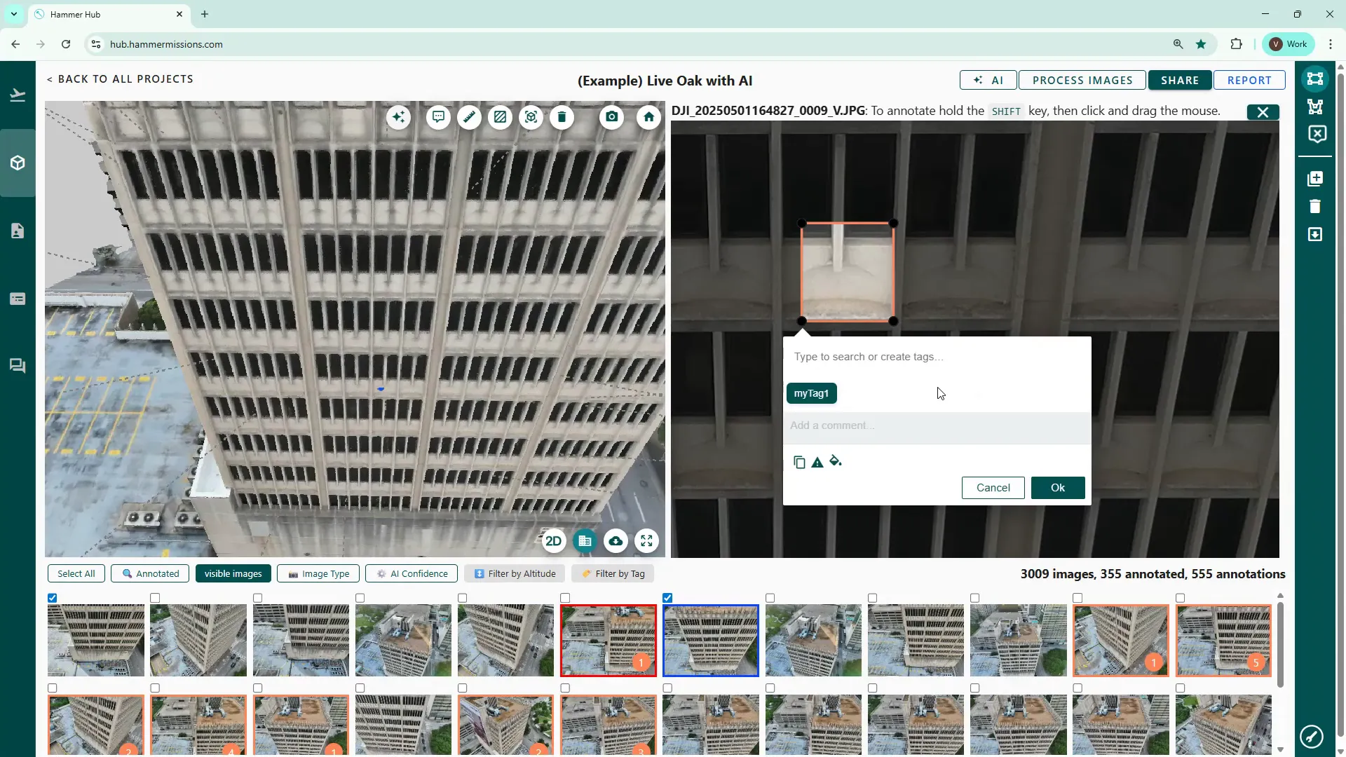
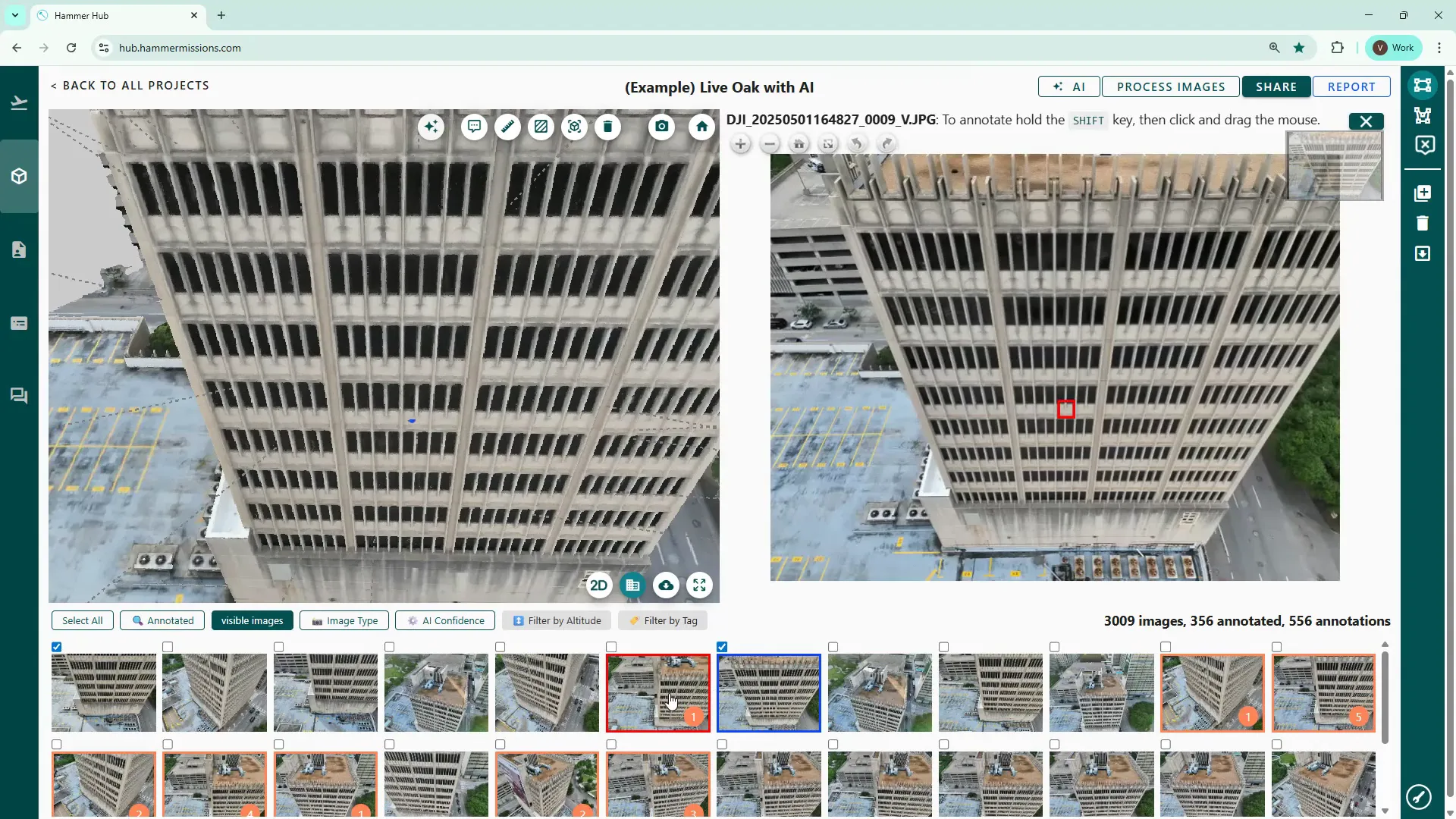
You can mark severe deficiencies as such by clicking the triangular icon. Marked thumbnails will be highlighted red and the boundary of the tagged area will also turn red, making high-priority items easy to find.
Filter by tag to only display images that match a particular tag. Use the annotated filter to see every image with any annotation — handy when preparing reports or doing a final quality check.

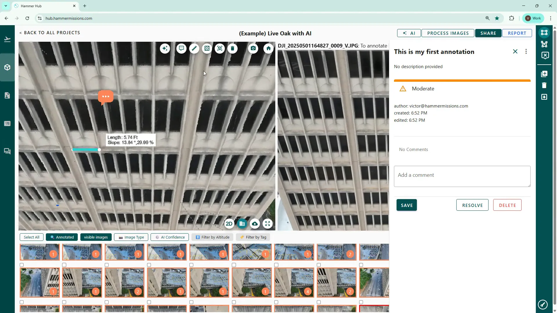
In addition to tags on the individual images, you can also create comments directly on the 3D model side. These are short text notes attached to model coordinates and can include urgency levels and further details.
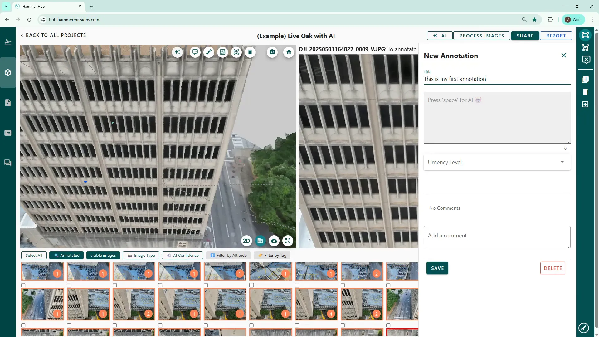
Use the speech bubble icon, (2nd left in the row of tool icons) enter your details and then click save. Click the annotation to edit or delete it later.
The platform includes built-in measurement utilities that are useful for measuring distances, area and volume. These functions can be particularly useful for example, in providing data to define the amount of repair work that might be needed.
To remove a measurement, click the bin icon then click on the measurement to remove it.
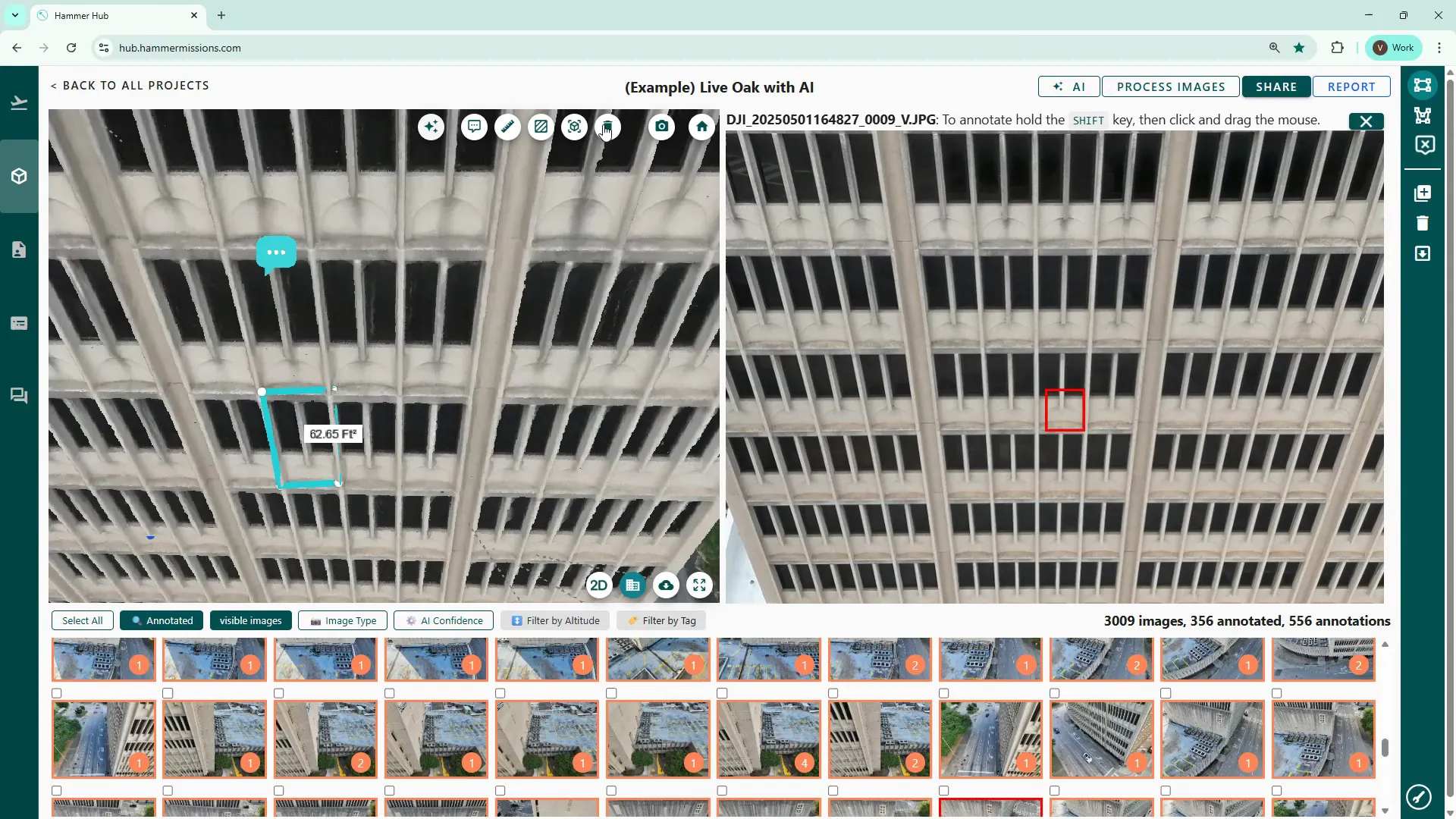
Delete area measurements using the delete button and clicking the boundary edge to confirm removal.
These tools and workflows will help you get the most from your Hammer Missions projects — streamlining inspection, annotation and measurement so you can deliver accurate, actionable analysis. If you follow the façade-by-façade approach, use the polygon/rectangle tagging tools and leverage the measurement utilities, you’ll significantly speed up your review process while improving the quality of your reports.